

So, you want your mobile or tablet to know where in the world you’re pointing it for a virtual reality or augmented reality application?
To draw 3D geometry on the screen in OpenGL, you can use the rotation matrixes returned by the respective APIs (iOS/Android). The APIs will also give you roll, pitch and yaw angles for the device.
What’s not easy to do through the APIs is to get three angles that tell you in general where the device is pointing – that is, the direction in which the rear camera is pointing. You might want this information to capture the location of something in the real world, or to draw a virtual or augmented view of a world on the screen of the phone. The Fireballs in the Sky app (iOS, Android) does both, allowing you to capture the start and end point of a “fireball” (meteor/ite) by pointing your phone at the sky, while drawing a HUD and stars on the phone screen during the capture process, so you’re confident you’ve got the right part of the sky.
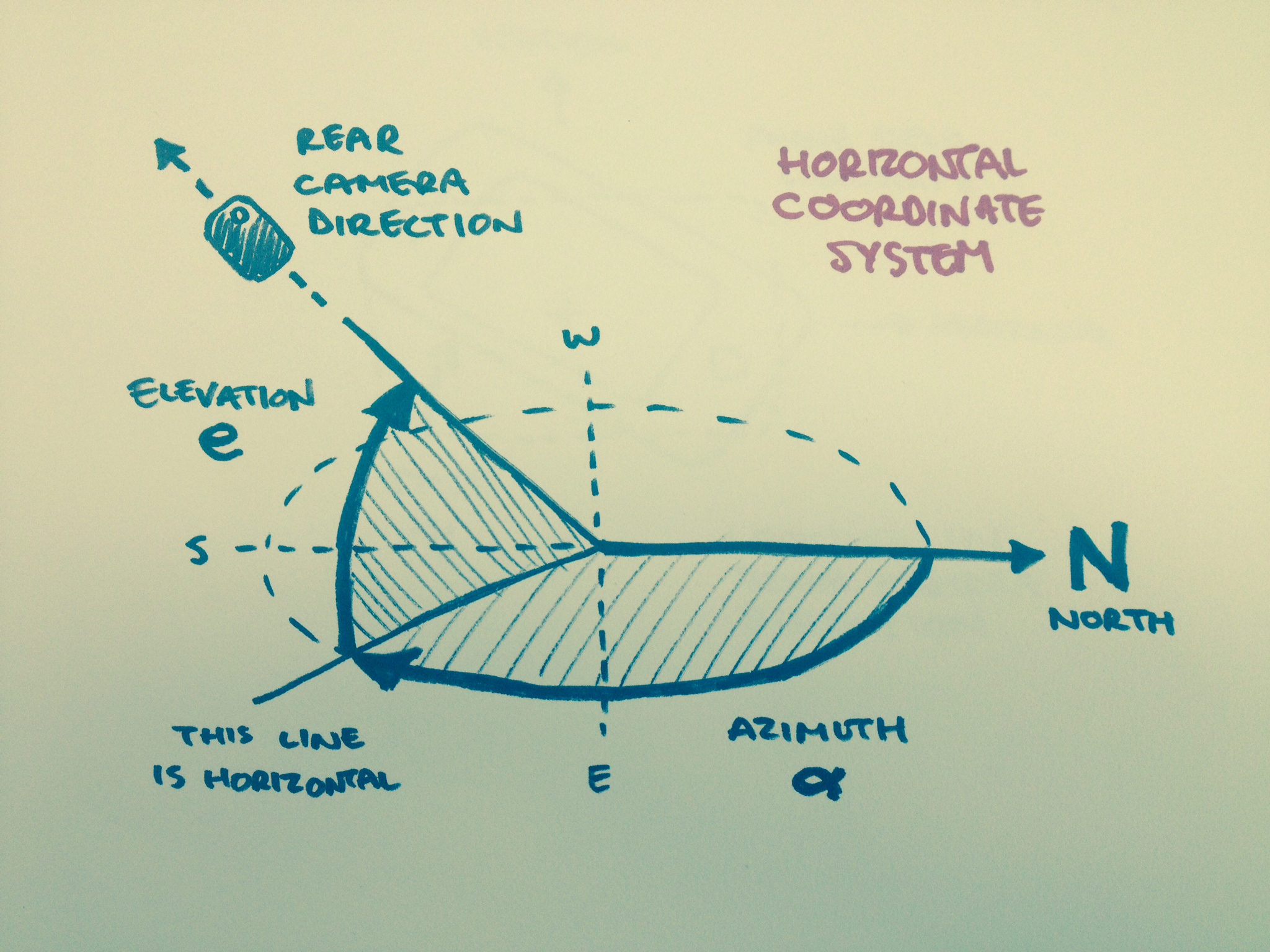
Roll, pitch and yaw tell you how the device sees itself – they are rotations around lines that go through the device (device axes). But in this case we want to know how the device sees the world – we need rotations around lines fixed in the real world (world axes). To know where the device is pointing, we actually want azimuth, elevation and tilt, as shown.
Azimuth and elevation together are commonly known as a horizontal coordinate system.

The azimuth, elevation pair of angles gives you enough information to define a direction, and hence capture objects in the real world (assuming the distance to the object does not need to be specified). However, if you want to draw something on the screen of your device, you need to know whether the device is held in landscape orientation, portrait orientation, or somewhere in-between; thus a third angle – tilt – is required.
Azimuth is defined as the compass angle of the direction the device is pointing. Elevation is the angle above horizontal of the direction the device is pointing. Tilt is the angle the device is rotated around the direction in which it is pointing (the direction defined by azimuth and elevation angles).
We can get azimuth, elevation and tilt with the following approach:
- Define a world reference frame
- Obtain the device’s rotation matrix with respect to this frame
- Calculate the azimuth, elevation and tilt angles from the rotation matrix
It will really help to be familiar with the mathematical concept of a vector (three numbers defining a point or direction in 3D space), and be able to convert between radians and degrees, from here on in. Sample code may be published in future.
Define a World Reference Frame
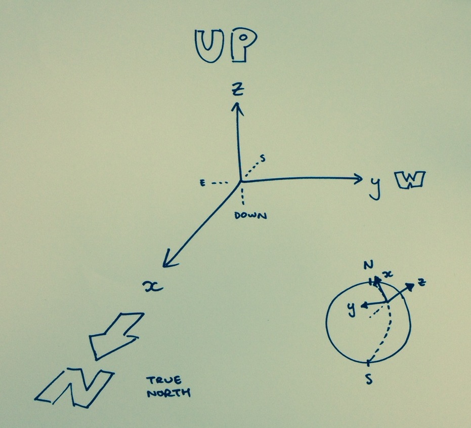
We’re somewhere in the world, defined by latitude, longitude and altitude. We’ll define a reference frame with its origin at this point. For convenience, we’d like Z to point straight up into the sky, and X to point to true north. Therefore, Y points west (for a right-handed frame), as shown here. We define unit vectors i, j, k in the principal directions (or axes) X, Y, Z, and we’ll use them later.
\[ \newcommand{\vect}[1]{\mathbf{#1}}
\vect{i} = \left[1,0,0\right], \vect{j} = \left[0,1,0\right], \vect{k} = \left[0,0,1\right]\]
Obtain Device Rotation Matrix

What we want eventually is an rotation matrix that is made up of the components of the device axes a, b, c, (also unit vectors) with reference to the world frame we defined. This matrix will allow us to convert a direction in the device frame into a direction in the world frame, and vice versa. This gives us all the information we need to derive azimuth, elevation and tilt angles.
We’ll describe the device axes as:
- a is “screen right”, the direction from the centre to the right of the screen with the device in portrait
- b is “screen top”, the direction from the centre to the top of the screen with the device in portrait
- c is “screen normal”, the direction straight out of the screen (at right angles to the screen, towards the viewer’s eye)
We can write each device axis as a vector sum of the components in each of the principal world frame directions, or we can use the shorthand of a list of numbers:
\[\vect{a} = a_i\vect{i}+a_j\vect{j}+a_k\vect{k} = \left[a_i,a_j,a_k\right]\]
The rotation matrix then has the form:
\[\mathbf{A} = \left[\begin{array}{ccc}
a_i & b_i & c_i \\
a_j & b_j & c_j \\
a_k & b_k & c_k \end{array}\right]\]
To get a matrix of this form in iOS, just use reference CMAttitudeReferenceFrameXTrueNorthZVertical and get the rotation matrix. However, the returned matrix will be the transpose of the matrix above, so you will need to transpose the result of the API call.
In Android, you will need to correct for magnetic declination and a default frame that uses Y as magnetic north, and therefore X as east. Both corrections are rotations about the Z axis. The matrix will similarly be transposed.
Calculate View Angles

We can calculate the view angles with some vector maths. The easiest angle is elevation, so let’s start there. We find the angle that the screen normal (c) makes with the vertical (k) using the dot product cosine relationship.
\[-\vect{c} \cdot \vect{k} = \cos\left(\frac{\pi}{2}-e\right)\]
\[e = \frac{\pi}{2} – \arccos\left(-\vect{c} \cdot \vect{k}\right)\]
Elevation is in the range [-90, 90]. Note also from the definitions above that such dot products can be extracted directly from the rotation matrix, as we can write:
\[\vect{c} \cdot \vect{k} = c_k \]

Next, we calculate azimuth, for which we need the horizontal projection (cH) of the screen normal (c). We use Pythagoras’ theorem to calculate cH:
\[1 = c_H^2 + c_V^2\]
\[c_H = \sqrt{1 – c_k^2}\]
We then define a vector cP in the direction of c, such that the horizontal projection of this vector is always equal to 1, so we can use this horizontal projection to calculate angles with the horizontal vectors i & j.
\[\vect{c}_P = \frac{\vect{c}}{c_H}\]

We then calculate the angle the horizontal projection of the screen normal (cP) makes with the north axis (i). We get the magnitude of this angle from this dot product with i, and we get the direction (E or W of north) from the dot product with the west axis (j).
\[\cos{\alpha} = -\vect{c}_P \cdot \vect{i} = \frac{-\vect{c} \cdot \vect{i}}{c_H}\]
\[\alpha’ = \arccos\left(-\frac{c_i}{c_H}\right)\]
\[\newcommand{\sgn}{\text{sgn}}
\alpha = \sgn\left({c_j}\right) \times \alpha’\]
Note that because we’ve only used screen normal direction up until now, we don’t care how the phone is tilted between portrait and landscape.

Last, we calculate tilt. For this calculation we also need to ensure the projection of the screen right vector aP onto the vertical axis (k) is always equal to 1. As above, we divide a by cH.
\[\vect{a}_P = \frac{\vect{a}}{c_H}\]
We take the angle between aP and the world frame vertical axis k.
\[\cos{\tau} = -\vect{a}_P \cdot \vect{k} = \frac{-\vect{a} \cdot \vect{k}}{c_H}\]
\[\tau’ = \arccos\left(-\frac{a_k}{c_H}\right)\]
\[\tau = \sgn\left({b_k}\right) \times \tau’\]
Note that as the elevation gets closer to +/-90, both the azimuth value and the tilt value will become less accurate because the horizontal projection of the screen normal approaches zero, and the vertical projection of the screen right direction approaches zero. How to handle elevation +/-90 is left as an exercise to the reader.
Sample Code
Sample code may be available in future. However, these calculations have been verified in iOS and Android.